
Whether we are talking about a project in London, a site in Dubai, or a facility in New York, the design process is the heartbeat of the energy sector. Here’s what we’ve learned about the journey from a blank screen to a high-pressure piping network.
Our Research Into the Modern Piping Design Process for Oil and Gas
You can’t just start welding pipes together. The piping design process in oil and gas is a rigid, multi-stage marathon. It always starts with the “Process Flow Diagram” (PFD). Think of this as the DNA of the plant. It doesn’t show where the pipes go; it shows what they do.
At Fluxiss , the team takes these blueprints and turns them into P&IDs (Piping and Instrumentation Diagrams). This is where things get real. Every valve, every flange, and every instrument is mapped out. If you miss one sensor here, the whole system in a UAE plant could face a shutdown. It’s all about the data before the metal.
Industrial Piping System Design Isn’t Just About Tubes
One thing that surprised us during research is how much industrial piping system design relies on chemistry and physics. You aren’t just moving “liquid.” You might be moving corrosive crude, supercritical CO2, or volatile hydrogen.
Firms like Fluxiss choose piping materials . You can’t use standard carbon steel for everything. In the high-humidity environments of Miami or the salt-heavy air of Aberdeen, engineers have to spec out stainless steel, duplex, or even specialized alloys to prevent “CUI” (Corrosion Under Insulation).
Cracking the Code: Following International Piping Design Standards
We used to think a pipe was just a pipe, but the law says otherwise. In the USA, we live and die by ASME B31.3 . If you are working on a project in the UK or Europe, you’re looking at BS EN 13480 .
What we found interesting about piping design standards in 2026 is the new focus on “Hydrogen Readiness.” Fluxiss engineers have told us that the standards are shifting. We aren’t just designing for oil anymore; we are designing for the transition. These codes dictate exactly how thick a pipe wall must be and what kind of pressure it can take before it becomes a safety hazard.
The Art of Piping Layout Design: Avoiding the “Clash”
This is the part we find most fascinating-the piping layout design . Imagine trying to fit miles of pipe, electrical trays, and walkways into a space the size of a city block.
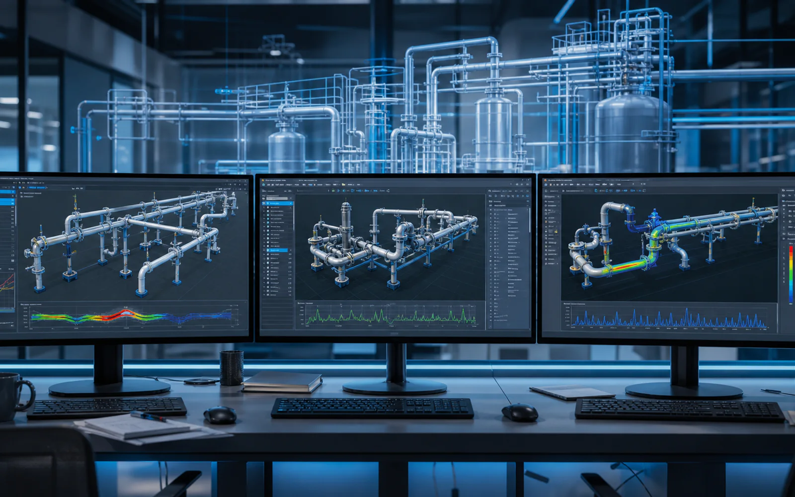
We’ve seen how 3D piping design software like AVEVA or Intergraph has changed the game. In the old days, you’d find out a pipe hit a structural beam during construction. Now, with “Clash Detection,” the computer screams at you if two objects occupy the same space. Fluxiss uses these piping engineering services to build the entire plant virtually in Dallas before a single shovel hits the ground in Abu Dhabi.
Smart Pipe Routing Design: The Path of Least Resistance
When we were looking into pipe routing design , we realized it’s a bit like a puzzle. You want the shortest route to save money on materials, but you also need to allow for “thermal expansion.”
Pipes grow when they get hot. If you route a pipe in a straight line between two fixed points, it will literally tear itself apart when the hot oil starts flowing. Engineers build in “Expansion Loops”-those U-shaped bends you see in refineries-to give the metal room to breathe.
Behind the Calculations: Pipe Stress Analysis and Flow
The math here is intense. Pipe stress analysis is where the “real” engineering happens. Fluxiss uses software like CAESAR II to simulate earthquakes, high winds in Chicago, or the massive weight of the fluid itself.
Then there are the flow calculations . You have to calculate “Pressure Drop.” If the pipe is too small, the pump has to work too hard and will eventually burn out. If it’s too large, you’ve wasted thousands of dollars in steel. It’s a balancing act that requires high-level expertise.
From 3D Models to Piping Isometrics and Engineering Drawings
Once the 3D model is perfect, the system spits out piping isometrics . To me, these look like 3D sketches on 2D paper. They aren’t drawn to scale, but they contain every single piece of information a welder needs: the exact length of the pipe, the angle of the weld, and the “Material Take-Off” (MTO).
These engineering drawings are the final hand-off. We’ve heard stories of projects failing because an isometric was misread. That’s why the quality control at Fluxiss is so tight; every line and symbol is double-checked against the 2026 standards.
The Fluxiss Way
Piping is the literal circulatory system of our modern world. From research and what we’ve seen of Fluxiss’s work across the USA, UK, and UAE, it’s clear that piping system design is moving toward a more digital, AI-integrated, and “green” future. It’s a mix of heavy-duty hardware and incredibly smart software.
Ready to Flow?
Whether you are building a new facility in the heart of London, upgrading a refinery in Texas, or launching a project in the UAE, the “metal spaghetti” needs a master chef. Don’t leave your piping system design to chance. From initial flow calculations to the final engineering drawings , you need a team that speaks the language of ASME and EN standards fluently.
Build Your System with Fluxiss – Get a Technical Consultation Today
Frequently Asked Questions
Safety and compliance with piping design standards like ASME B31.3 are paramount. Interest is built through precise pipe stress analysis to prevent leaks. Desire for a long-lasting system is achieved by selecting correct piping materials.
Fluxiss Editorial is part of the Fluxiss engineering team, delivering pipe stress scopes across the USA, UK, UAE and Europe.


Let's Build Something Great Together.
Partner with Fluxiss for engineering that holds up - under pressure, under load, under scrutiny.